Common Questions
Courses
Tips for Cutting Thick Materials
NOTE:When cutting very slowly in thick or thin materials, you need to be careful that you do not cut a hole through the floor of the tank. If you think this could happen, protect the floor by placing sacrificial layers of steel or scrap plate on the floor, making sure that there are no gaps where the stream could get between the scrap and cut the floor of the tank.
It is possible to cut a hole in the floor of the tank if you left the head on in one position and went to answer the phone and forgot about the waterjet. The jet is powerful enough that it will eventually cut a hole in anything in its way, including the floor of the tank. So always make sure you are thinking about how much energy is still available after going through the material you are cutting.
- Always do a few test cuts of the different sections of the part at the speeds you expect to cut at. So take the part and look for inside corners, outside corners, radii etc, then make a small part that will have all these features and program it and cut it so you get an idea as to how these will look on the finished part.
- Write down the home position.
- Practice some job interrupt as you may well need to do this in a long cut.
- Decide where you will pause the program if you have to in the middle of the cut. In other words, is there a section of the part that is not critical to tolerances. In your case of the gear, the very inside and tip of each tooth will never come into contact with anything and hence will be in fresh air. As a result this would be a good place to pause the program and do any tests.
- Once you have the part on the table, run the full program with water only at a high speed. This will mark the material and confirm that the part will fit on the piece of material and your set up is correct.
- If you have to stop the program or you get a power failure do not rely only on the home position you wrote down. Rather start the program and run the first part with water only and check that it follows the cut that you have already done. You may also want to move it to another portion of the program and check that it still lines up there too. I am always concerned that when restating a program you could be a few to several thousands of an inch out of position and this might not be good.
- As you cut through the part, take a hack saw blade and grind off all the teeth so you have a thin long gauge that will fit down the kerf that has been removed. Let’s say the material is 6” thick. Put a mark on the blade at say 6.5”. Then take the blade and insert it into the cut and with the bottom of the blade sticking out the bottom, slide the blade along the tool path and check that the material is cut all the way through. You of course have to make allowance for grates. But this will give you a good guide as to the status of the bottom of the cut.
- Make sure your abrasive is calibrated and set.
- Use the coarsest hard rock garnet you can with your orifice nozzle combination. In your case try to use 50 mesh hard rock with a 40th nozzle.
- Make sure the pressure is correct.
- Ideally put in a diamond orifice as this is a much more reliable way to go especially when the material you are cutting is costly.
- Check the condition of the nozzle.
- Make sure the cutting head is vertical as if it is not the tolerances of the part will be compromised. To do this line up the head or pierce a small hole in thin material. Then raise the cutting head up and the stream should go through the hole. If the head is not vertical it will ‘walk’ out of the hole and the direction of the cut will tell you how your cutting head needs to be adjusted.
Tips for Cutting Thick Materials
Probably the first thing you should check is your orifice. If it is blown out, it will widen the cutting stream considerably. The easiest way to tell whether or not you have a bad orifice is to look at the stream of water coming out of the nozzle at full pressure. To do this check, raise the cutting head above the level of the water about six inches. Turn your pump on and bring it up to operating pressure then manually turn on the cutting head and observe the stream. If the stream looks fairly small all the way down to only about 0.25″-0.5″ at the bottom then your stream is considered good. However if your stream fans out very wide immediately at the tip of the nozzle then you know you have a problem with your orifice and/or your nozzle.
Another way to check your orifice and eliminate the possibility of a bad nozzle is to remove the nozzle from the cutting head and then proceed to use the first method described above. Although this time you should see a very thin stream, almost like a needle.
The next item to check would be the mixing chamber. First you should visually check that it is intact by removing it, secondly you should check that it is in spec while you have it out. You should gauge the hole where the water enters the mixing chamber. If it is out of round, blocked or enlarged, it would affect the quality of your water stream.
How do I install / replace an orifice?
The orifice of the cutting head is the smallest diameter of the cutting stream and accelerates the water velocity drastically up to 2200 mph.
When replacing an orifice, the most important part of the procedure is the alignment of the new orifice itself. If it is not properly aligned with the incoming stream of high pressure water, its lifetime will be drastically reduced. If installed improperly, you may ruin an orifice within the first few minutes of usage.
Therefore it is very important to place the orifice in the cutting head correctly and to introduce the orifice to pressure slowly over a period of time starting at zero and “breaking in” the orifice up to maximum cutting pressure.
This last step is one of the most important things to remember when replacing an orifice.
If a new orifice is not “broken in” properly, the jewel will be exposed to maximum pressure too quickly and may actually break, forcing you to replace the orifice yet again.
First make sure that the pump is shutdown and that there is no pressure in the lines. Then isolate the high pressure of the cutting head by turning the hand valve clockwise all the way. This will prevent any high pressure water from reaching the cutting head in the event that someone walks by and turns on the pump. Remove the bottom portion of your cutting head; this could be an abrasive head or a water-only head. This needs to be done with two crescent wrenches. One wrench holds the cutting head in a fixed position while the other one rotates the body itself.
When the cutting head is off, you will see the orifice located in the bottom of the body. Remove the orifice by using a set of needle-nose pliers. If you have an orifice that is shaped like a puck and slides in a tight machined pocket you have to remove the orifice from its body by tapping the body gently on a notebook or something similar that can dampen the shock of the tapping. You should see the orifice slowly begin to slide out.
Once the orifice is out you can clean the body with a product like Simple Green to remove any old residue of Blue Goop. After this we can put the new orifice in the body. Make sure that the jewel faces UP. If you are using a “puck” shaped orifice you have to make sure you do NOT use any Blue Goop on the bottom of the orifice.
Now make sure you clean the threads of the adapter where the cutting head is getting mounted to and re-apply some fresh Blue Goop.
Now screw the body back on to the adapter until it bottoms out. Use two crescent wrenches again to tighten this up. When this is tight we want to open the hand valve again, by turning it counter-clockwise all the way, and then back clockwise a quarter turn.
Follow the steps for breaking in a new orifice.
How do I break in a new orifice?
1. Open up the cutting head by switching the water switch on the controller to Manual. This will open up the cutting head, so as soon as intensified water begins flowing from the pump it will immediately come out of the cutting head.
2. Walk over to your pump and if possible set your pump to low pressure mode. If this is not possible, you should just turn the pressure compensator all the way down (counter-clockwise) so the pressure would be set at zero.
3. Start the pump and intensifier and you will see a stream of water coming out of your cutting head with the pressure setting that your low pressure is set at. If you turned down the compensator in the previous step you should slowly increase the pressure with the compensator till you see water coming out of the cutting head. Increase the pressure to 10,000 psi. On most pumps this will be around 500 PSI hydraulic pressure.
4. Walk back to your controller and turn the water off and on several times by using the switch. Check for leaks while you are doing this.
5. Leave the head open and walk back to the pump and increase the pressure to the cutting pressure you normally use. This can be done by increasing the compensator further or by switching to high pressure mode on the controls of the pump.
6. Walk back to the controller again and switch water on and off several times.
7. Now you are set to start cutting again and you have properly seated the new orifice.
How can I prevent clogging in my abrasive line and how can I remedy a clogged line?
1. One way you might see an instant clog in your abrasive line is if you touch your material with the tip of your nozzle. When this happens you will have too much back pressure against the flow of abrasive and it will cause the abrasive to get wet and back track up your line. When using a height sensor, check the distance between your nozzle and material.
2. If your breathers at your mini hopper are clogged or dirty, then the pressure that pushes the abrasive over the highest point of the whip will not be able to exhaust. This will cause the abrasive in your mini hopper to become pressurized and create extra force behind your abrasive flow going to your cutting head. The extra force will push more abrasive to your cutting head than necessary and could contribute to clogging issues.
3. You will notice abrasive blockages when your needle and seat start to go bad. As the slow drip of water starts to leak past your needle and seat, it will wick up the abrasive line causing the wet abrasive to block the nozzle and mixing chamber.
4. Occasionally you should clean the hollow breather tube located inside your mini hopper by removing the aluminum top and blowing compressed air through the hollow stainless steel tube. Sometimes when the abrasive in the bulk feed hopper runs out, it spits into the mini hopper with higher force causing some abrasive to go down the breather tube. When abrasive gets trapped in the breather tube, it blocks the air flow that is needed to neutralize the vacuum coming from your cutting head.
5. If you have a bad orifice or an orifice that is oversize or out of spec, it will cause the vacuum in the cutting head to diminish. This causes the abrasive to slow down and increases the probability of a blockage.
6. A bad mixing chamber can also cause your cutting head to lose vacuum. You will notice your mixing chamber is bad when you remove it and inspect the inlet water hole on the top. If the hole is larger than 0.090” then it is out of specification.
7. Another reason why you might be getting abrasive blockages is if your abrasive feed rate is set too high. When you change the orifice and nozzle to a smaller size it also means you have to turn down your abrasive feed rate. The abrasive feed rate to the cutting head might be more than the rate that is coming out of the cutting head and this will cause the abrasive to back up and block the flow.
8. It is also important to make sure that the abrasive inlet tube in the cutting head is tight with no way for air to leak around it or you will get a loss of vacuum. If you have the Accustream A2 style cutting head then you should insure that the secondary or opposite feed tube is properly blocked not allowing any air through if it is not being used.
Get in touch
Product Brochures
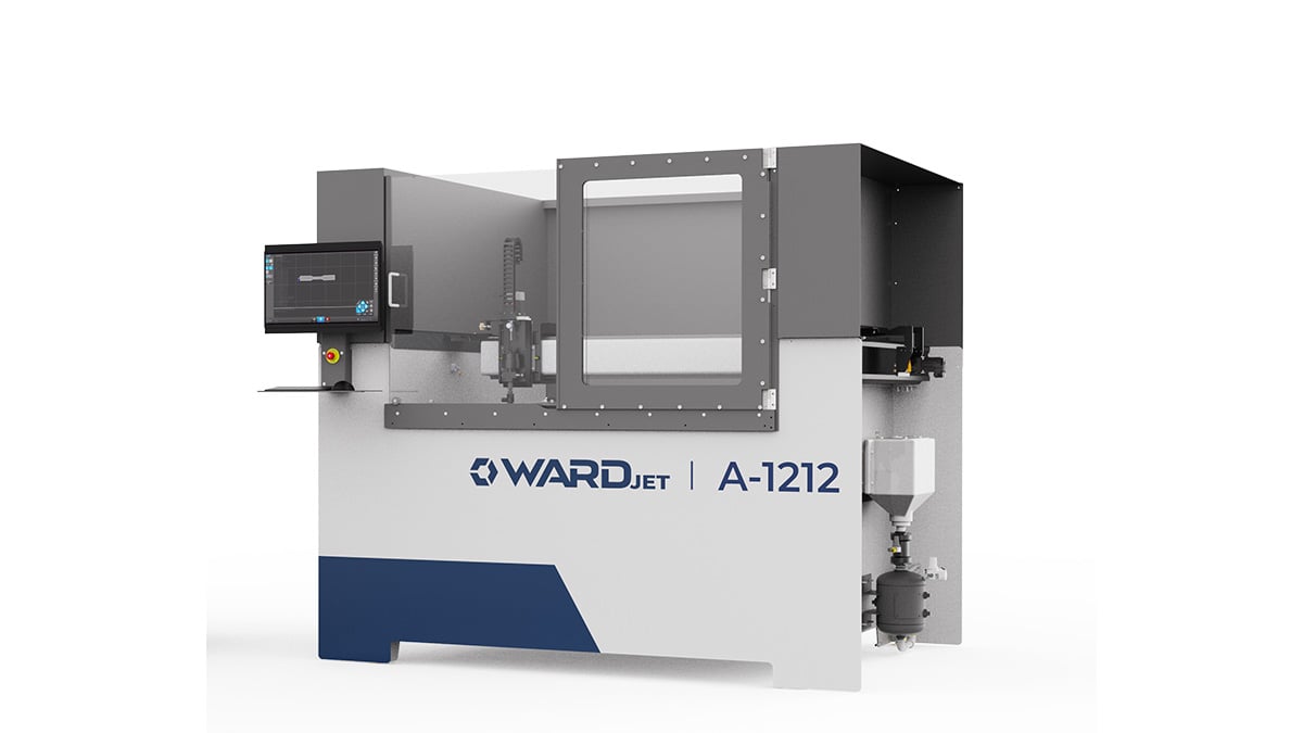
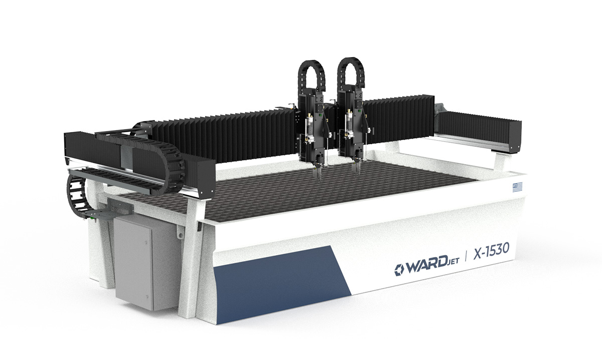
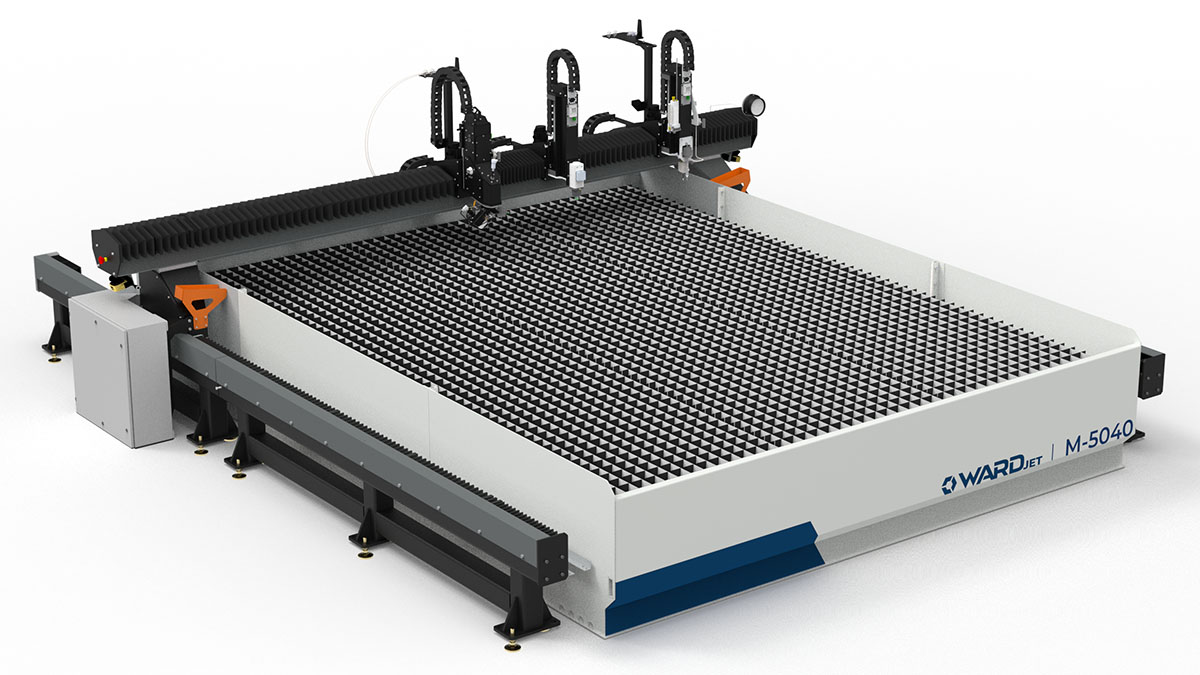
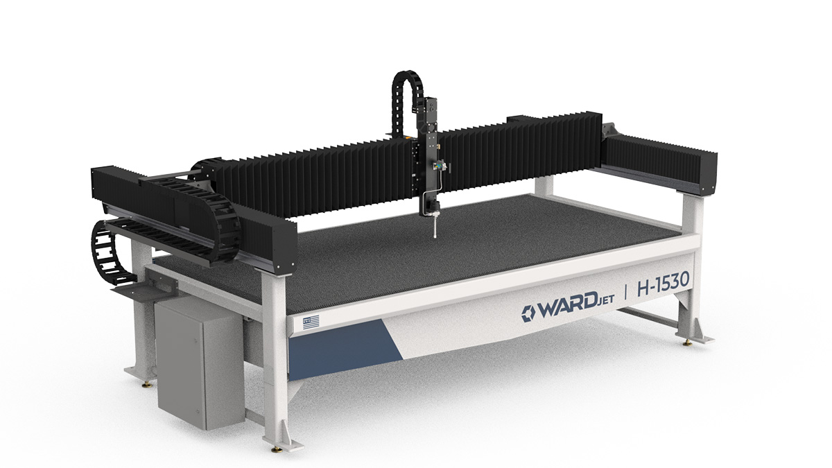
Get a copy of WARDJET's latest product brochure. Learn all about our extensive range of WARDJet CNC waterjets. Choose between our 6 big series - A-Series, X-Series, M-Series, H-Series, J-Series, and L-Series.

