
Precision and Quality
Courses
Overview
For successful abrasive waterjet cutting, there are several factors at the cutting head that determine the precision and quality of the waterjet stream and will affect the quality of part you are able to cut with an abrasive waterjet. There are other factors that will go into cutting a precise and accurate part (machine design, controls, software and high-pressure pump) that will be discussed in other chapters. This chapter will focus on the cutting head and the waterjet as it interacts with the work piece.
Factors affecting precision & quality
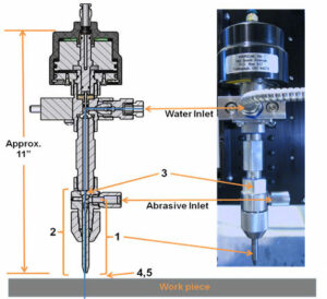
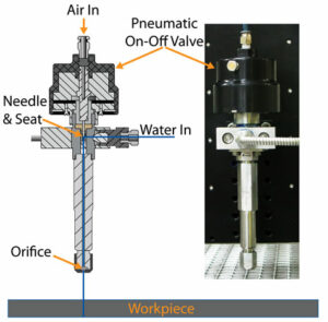
Figure 1 – Abrasive and Water Only Waterjet Cutting Heads
1 - Abrasive mixing tube length
A longer abrasive mixing tube (a.k.a. abrasive nozzle) produces a more coherent waterjet stream. The optimum mixing tube length is 3″ – 4″ (75 mm – 100 mm).
2 - Alignment of components
The orifice, mixing chamber and abrasive nozzle must be precisely machined and fit perfectly together to avoid damage of consumables by the waterjet stream.
3 - Precise orifice
The inside of the abrasive nozzle must be machined to ensure perfect alignment with the waterjet stream. See “Waterjet stream’s effect on accuracy” section of this chapter for more information.
4 - Diameter of stream
A small diameter waterjet stream, as produced by a .010″ (0.25 mm) orifice produces an efficient, high-quality stream. As a trade-off, cutting speeds are slower than when using a 0.014″ (0.36 mm) or larger orifice, since less water and abrasive are used. See Chapter 2 “Relationship Parameters” for more information on orifice selection.
5 - Low, controlled stand-off from work
Maintaining a close distance between the nozzle and the work piece, between 0.040″ and 0.060″ (1.0 – 1.5 mm), is critical for producing accurate parts while also getting the maximum efficiency from the waterjet. Cutting closer to the material limits the amount of atmosphere that the jet has to travel through before reaching the work piece. This limits the expansion of the waterjet stream, since as the jet expands, the effective power of the jet is reduced. Cutting speeds will need to be reduced to compensate. If the distance between the nozzle and the work piece is increased by ¼”, cutting speeds must be reduced by approximately 20% to achieve similar results with respect to tolerance and edge quality. Cutting under water with CNC height control will allow for ultimate control of the waterjet stream.
Creation of the abrasive waterjet stream
Following is a description of how the abrasive waterjet stream is created in the cutting head. The numbers indicated below refer to the numbers in Figure 2.
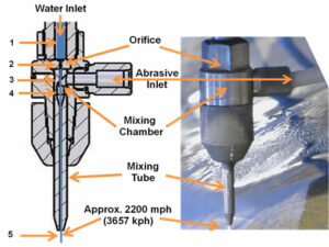
Figure 2 – Close-up of the abrasive waterjet cutting head
1 - Water Pressure
Water pressurized at 50,000 psi or greater enters the cutting head at relatively slow speed, in the order of a few feet per second. (See “How It Works” for more information on how this water pressure is created and transmitted to the cutting head.)
Stream Conversion
The water is forced through an orifice that has a small diameter orifice, anywhere from 0.004″ to 0.045″ depending upon the application. These orifices are made of extremely hard material, such as diamond, sapphire or ruby. This step converts the water stream from a high pressure stream to a high velocity stream. At this point the water is moving in excess of 2200 miles per hour (3657 kilometers per hour).
3 - Venturi Effect
The high velocity of the jet creates a Venturi effect, or vacuum, in the mixing chamber located immediately beneath the orifice. Abrasive, typically garnet, is metered from a mini-hopper through a plastic tube down to the cutting head and is sucked into the waterjet stream in the mixing chamber. Cutting speed will increase with more abrasive until a saturation point is reached where speed starts to decrease. If the abrasive amount is increased too high, ultimately the mixing tube will clog.
One of the exciting advancements in waterjet cutting in the past few years is the appearance on CNC- controlled abrasive metering systems. These systems precisely control the amount of abrasive that is allowed to flow to the cutting head. During the piercing process, cutting pressure and abrasive amount are reduced and the cutting head makes small, circular motions in the X and Y axes. This piercing procedure allows for difficult applications, such as piercing of glass and stone, to be processed with relative ease.
4 - Waterjet stream & abrasive mixture
The abrasive is fully mixed in the waterjet stream and is accelerated to approximately the speed of the waterjet stream. This step does steal some energy from the waterjet stream, slowing it down slightly.
5 - Accelerated Erosion
The abrasive waterjet stream exits the mixing tube with extreme speed and power. The abrasive erodes the material to be cut. The process is referred to as “abrasive waterjet cutting” because it is the abrasive that is actually doing the cutting. The water’s role is simply to give speed and power to the abrasive. In pure waterjet cutting, used for soft materials like foam and food, the force of the waterjet stream alone is enough to cut the material and abrasive is not required.
Affect of speed upon kerf angle
Kerf angle, or bevel, refers to the dimensional difference between the top and bottom of the cut cross-section. Cutting too fast will result in a wider kerf width at the top of the cut cross-section and a narrower kerf width at the bottom of the zone. In Fig. 3, from left to right, cuts were done at 26 inches per minute (ipm), 14 ipm and 9.7 ipm (660 millimeters per minute [mm/min], 355 mm/min and 246 mm/min). All other parameters were held constant (pressure 60 kpsi, 0.060″ standoff distance, 1.3 lb/min abrasive [4134 bar, 1.5mm and 600 grams/min]). At the top of the cut, kerf width was similar, around 0.044″ (1.12 mm). The difference between top and bottom going from left to right was 0.017″, 0.013″ and 0.011″ (0.43 mm, 0.33 mm and 0.28 mm). This shows the decrease in angularity as speed decreases.
Figure 3 – 3/4″ (20 mm) Aluminum with 3 different cut speeds

High Speed, Widest Kerf at Top, Narrowest aat Bottom
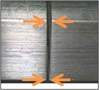
Medium Speed, Wider Kerf width at top than at bottom
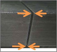
Slower Speed, Similar width Kerf at top and bottom
The picture below shows one additional cut that was done extremely slowly (1 ipm or 25.4 mm/min) to demonstrate that when speed is decreased enough, the kerf width at the bottom of the part will be larger than at the top. In this example the kerf width at the bottom was 0.014″ (0.36 mm) larger than at the top.
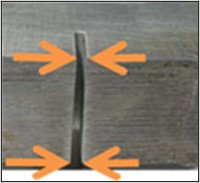
Very slow speed, Narrower kerf width at top, Wider at Bottom.
Drag of waterjet stream and cut quality
Increasing feedrate results in increased trail back of waterjet stream. This concept is shown in Figure 5 below. Rougher edge quality is the result of more shearing action versus erosion action of abrasive at slower speeds. Modern controllers allow the user to adjust cut quality based upon part requirements. High-precision holes can be cut slower for a smoother, straighter cut. Faster cutting speeds with rougher edge quality can be used on less critical areas.
Seperation Cut
Through Cut
Clean Cut ± 0.010"
Good Finish
Excellent Finish ± 0.005"
Effect of Nozzle Height
For best cut quality, an optimum distance between the nozzle and the work piece should be maintained. Typically, between 0.0625″ and 0.125″ (1.5 – 3.0 mm) is the optimum height for abrasive waterjet cutting. As the distance increases above 0.125″, rounding on the top edge of the cut will result. This occurs because the waterjet stream looses coherence as it travels through open air. Increased nozzle height will also result in increased kerf angle. If the distance between the nozzle and the work piece is increased by ¼”, cutting speeds must be reduced by approximately 20% to achieve similar results with respect to tolerance and edge quality. Automatic height control is the most reliable and accurate way to maintain proper standoff distance. Figure 7 shows that if the nozzle height is increased too far, the jet will not have enough power to fully penetrate material that it would easily cut at much lower heights.
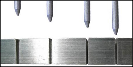
Figure 6 - 3/4" Aluminum with cuts at various nozzle heights, same speed
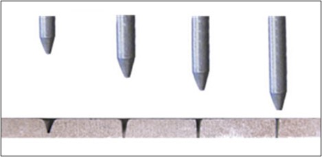
Figure 7 - Increasing nozzle height to point of no jet penetration
Effect of speed on inside corners
Since the waterjet is a non-rigid cutting tool, inside corners on parts can exhibit a certain amount of overcut on the bottom, or exit, side of the part. This can be reduced by decelerating into the corner and slowly accelerating, allowing the bottom portion of the jet to catch up with the top portion around the corner. The waterjet control must have the ability to do this automatically.
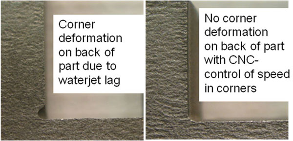
Figure 8 - Corner speed too fast
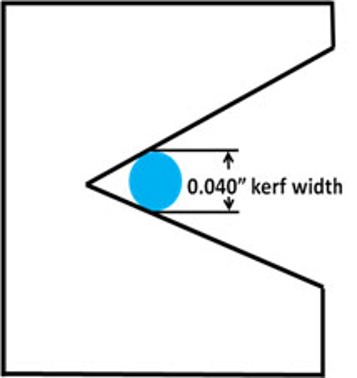
Tight radii
Since the waterjet stream is a round tool, with a diameter between 0.030″ and 0.040″ (0.76 mm and 1.02 mm) for abrasive waterjet cutting, creating any inside corner that is perfectly square is impossible. CAM software will typically read geometries and give a user the option to automatically place a very small radius on these corners. This will avoid damaging the part and reduce processing time, as radii are faster to cut than square corners. For very acute angles, the actual part that is cut may differ significantly from the original drawing and should be considered for form, fit and function before processing.
Lead-in and Lead-out types
Piercing in the scrap area of material and “leading-in” to the actual geometry to cut is standard operating procedure in most waterjet applications. This avoids placing a large blow-out blemish from the initial piercing on the surface of the part. At the end of a cut, a lead-out may be required to remove any “nib” from the lead-in area.
Various types of lead-ins and lead-outs can be experimented with for different materials and thicknesses. Figure 9 shows a few examples of lead-ins and leads-outs.

Figure 9 – Different lead-in/lead-out types.
- Number 1 (straight line lead-in with very short straight line lead-out) is desirable for any sharp corner.
- Number 2 (arc lead-in with short arc lead-out) is good for thinner and softer materials.
- Number 3 (straight line lead in with no lead-out) gives good results on thicker, harder material.
- Number 4 is an example of a straight line lead in with short arc lead-out. CAM software should have the flexibility to combine different types of lead-ins and lead-outs should the user wish to experiment.
Reducing lead-in/lead-out witness marks
At the end of a cut, a small nib may remain on the bottom portion of the cut in the lead-in/lead-out area. Because of the lagging effect discussed previously, when the jet reaches the end of the cut, the top portion of the jet will find the path of least resistance, and effectively “jump over” a small bit of material leaving a nib. With the more sophisticated controls and software available today, this can be reduced by decelerating at the end of the cut to allow the bottom portion of the jet to catch up with the top before reaching the end of the cut. Figure 10 below shows examples of a large nib because of too much speed at the end of a cut and an example of a minimal witness mark with appropriate slow down at the end of the cut.
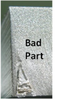
Figure 10 - Bad part on left showing excessive nib
Good part on right with minimal witness mark
Waterjet stream's effect on accuracy
Mixing tubes are made of extremely hard materials such as sintered boride or more commonly composite tungsten carbide. However, the nozzles are subject to wear and their cost must be taken into consideration for job costing. The orifice of a mixing tube will typically increase in diameter by about 0.0001″ per hour of cutting because of the erosion of the abrasive flowing through the nozzle. If this wear occurs in an even fashion, up to 120 hours of cutting can be realized with a nozzle. The biggest factor affecting nozzle wear is the material from which they are made. Controls allow for compensating for this wear by allowing the operator to change the tool offset.


Figure 11 – New and used mixing tubes. Note orifice on right is off-center.
If the wear of the nozzle is not symmetrical, the waterjet stream will also not be round. This will result in wider tolerances when cutting in a certain direction.
The tolerance requirements of a job will dictate the actual number of hours a user can expect from a nozzle. The nozzle can, of course, be set aside and used later for looser tolerance jobs. Control software should allow the ability to track hours on individual components to make consumable management easier. See Figure 12 below for an example of orifice and mixing tube tracking.
Get in touch
Product Brochures
Get a copy of WARDJET's latest product brochure. Learn all about our extensive range of WARDJet CNC waterjets. Choose between our 6 big series - A-Series, X-Series, M-Series, H-Series, J-Series, and L-Series.